
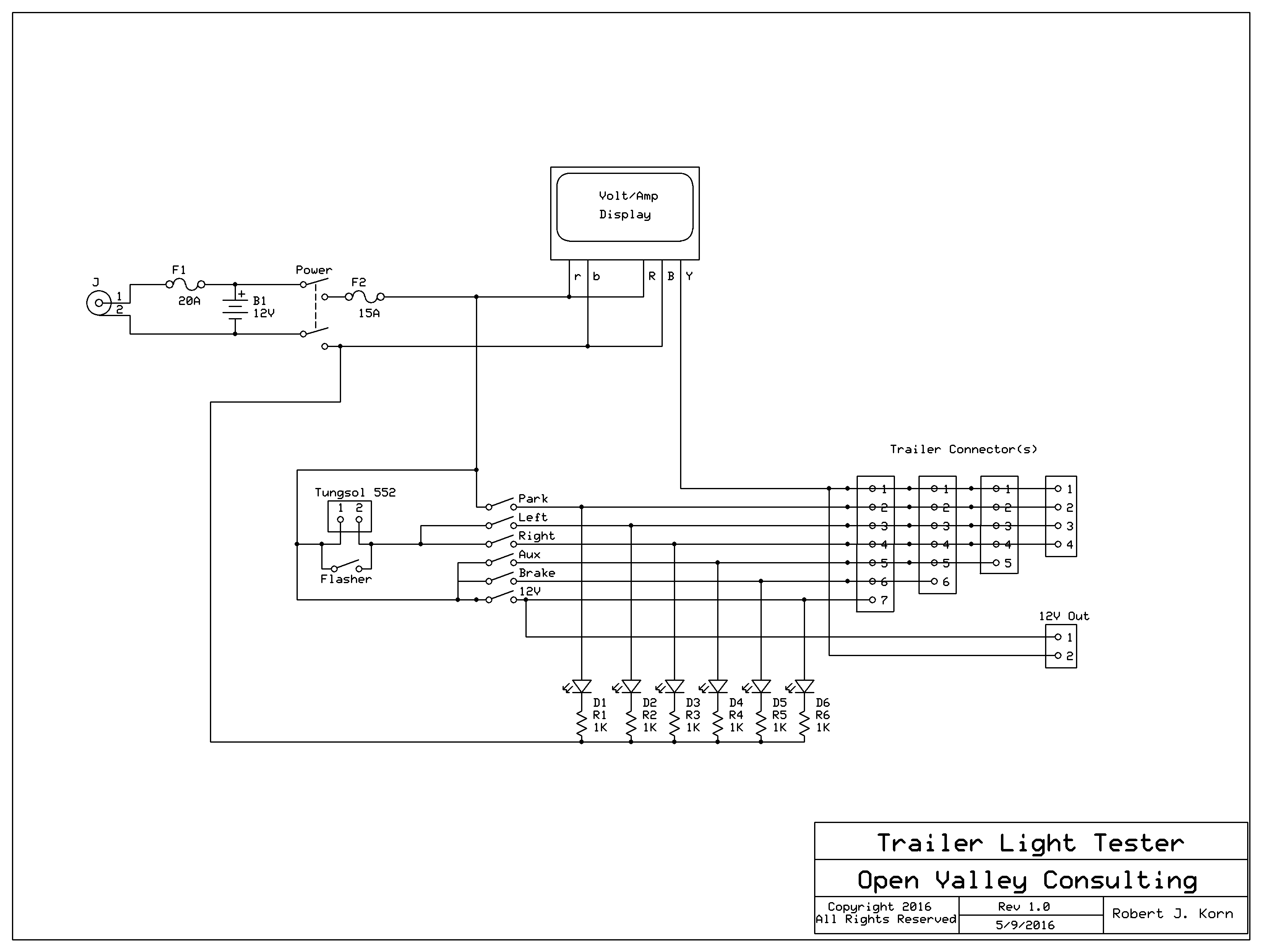
Trailer Light Tester Schematic
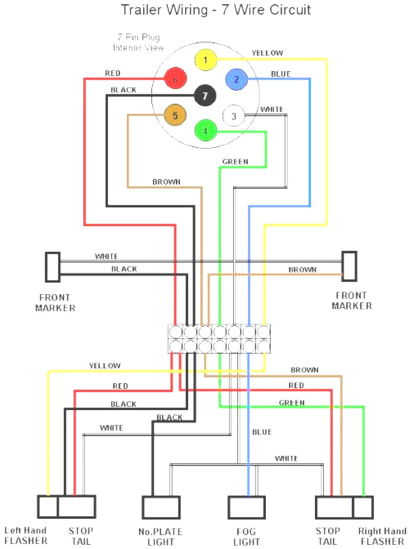
Wiring diagram for trailer 7-pin connector. Wiring diagram lighting trailer plug/socket 7-pin universal 12 volt. As the name partly gives away, the 7-pole plug consists of seven different connections. In the illustration below, these connections are indicated by different colors. Using these colors, in combination with the information below.
wiring diagram box trailer lights Trailer wiring lights diagram light
caravan or trailer's road lights and any internal auxiliary equipment. In the past, this was commonly considered a straightforward task for a competent DIY person. In recent years, however, the increasing complexity of vehicle electrical systems has made it more and more difficult to obtain and interpret the technical information necessary to.

Trailer Light Wiring Diagram 7 Flat Load Center Maia Schema
This special harness is used with most utility and boat trailers. With the right connection, the running lights, brake lights, and turn signals will all work properly. The other pin is used for the ground wire. To help you get started, I have some tips for installing 4-pin trailer wiring.
Trailer Wiring Care Trailering BoatUS Magazine
Wiring diagram: A wiring diagram is essential to guide you through the process and ensure that you connect the wires correctly. Having these tools on hand will make the process of wiring trailer lights much easier and more efficient. Make sure to have all the necessary tools before you begin the installation to avoid any delays or complications.

Partsam Rectangular Triple LED Trailer Tail Light Red RV Camper
7 pin 12N Wiring Diagram. The 7 Pin Plug is known in the industry as the 12 N type plugs, that are used for road lighting only. This is currently the most popular plug used for towing as it does the lighting on most trailers and caravans. This is slowly being replaced by the European 13 pin plug and will become less popular as the reverse light.
Wiring Diagram For Trailer Lights
Attach the light, pull the small black wire near the dual wires that go toward the rear light. Grab the little clips included in the kit to connect the wire moving from the side light to the central wire that moves toward the rear lights.

Boat Trailer Light Plug French House Wiring Diagrams For Lights
At a minimum, all trailers need at least 4 functions: Tail lights, Brake lights, Left & Right signals. 4 wires will give these functions, so the simplest scheme is a 4-pin connector. The most common 4 wire connector is the 4-Pin Flat Connector as shown here.

Wiring Diagram For 07 Gmc Tc5500 Trailer Light Database
With a basic trailer light wiring diagram, you can easily connect the necessary wires and get your lights up and running in no time. The wiring diagram for trailer lights typically shows the layout of the different wires and components, including the main taillight assembly, turn signals, brake lights, and ground wire.
XM381 12 Volt Civillian Trailer Wiring
0:00 / 3:12 How To Wire Trailer Lights Del City 1.67K subscribers Subscribe Subscribed 267 Share 113K views 6 years ago Del City How Tos Wiring trailer lights can be a big task, and you want.

Divine Enclosed Trailer Wiring T8 Led Tube Connection
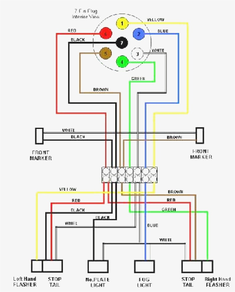
Here are two wiring diagrams for the 7 pin 'N' type trailer electrical plug. The first diagram is a simple set up of two brake lights, two indicators and two side lights. Click on the image below to enlarge it. The second diagram shows two brake lights, two indicators, two side lights and a fog light. Click on the image below to enlarge it.
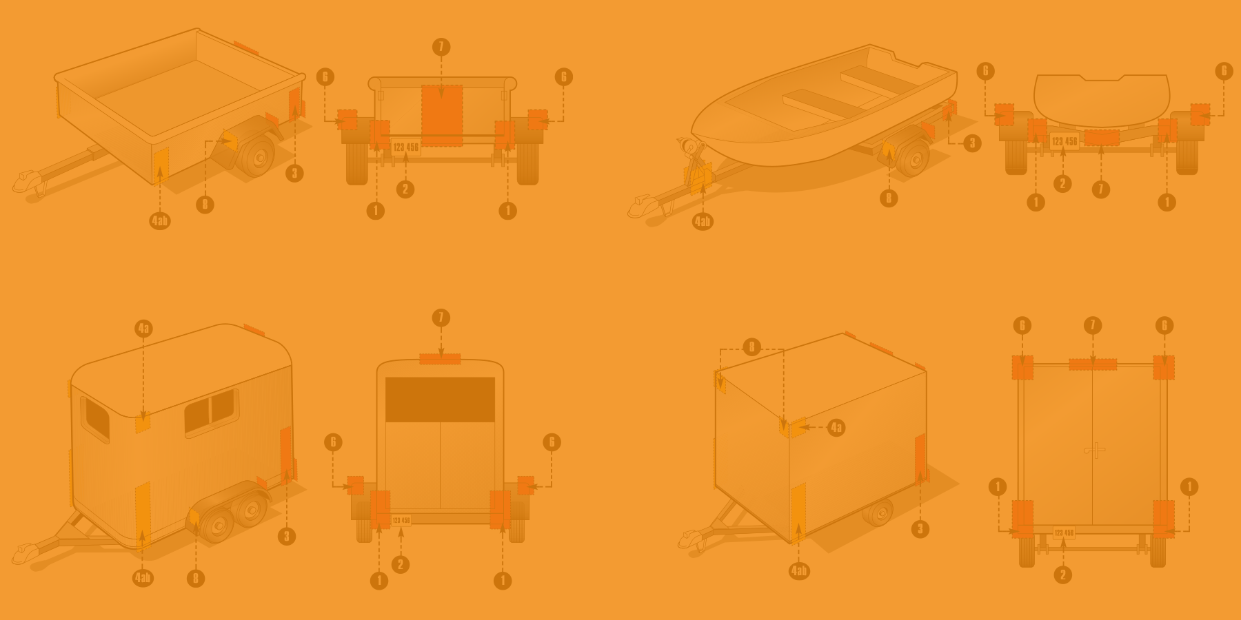
Trailer Light Requirements Custer Products
Trailer Hire 7 pin 12N wiring diagram. 12 N type plugs are used for road lighting only. This is currently the most popular plug used for towing as it does the lighting on most trailers and caravans.
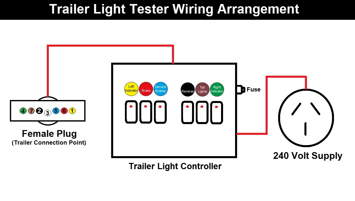
Trailer Light Tester Trailer Plug Extension
While the basic configuration is a 4-way flat connector with one female and three male ends, you may come across connectors with up to seven pins for additional functions requiring wiring, including electrically actuated brakes, power source for a winch, etc. Basics: 4-Way Connector This is the most common scenario.

Rv Trailer Light Plug Wiring Diagram Trailer Wiring Diagram
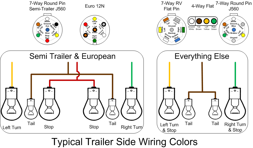
Brown: Tail/running lights White: Ground wire Blue: Brake controller output Black: Battery hot lead Purple: Reverse lights RV Standard Green: Tail/running lights Yellow: Reverse Lights Brown: Right turn/brake light White: Ground wire Blue: Brake controller output Black: Battery hot lead Red: Left turn/brake light

Trailer Wiring Schematic 7 Way Free Wiring Diagram
Diagrams Of Trailer Electrical Wiring components Ifor Williams Junction Box Wiring Diagrams for 13 pin and 7 pin sockets A 13 pin socket on a trailer with reversing lights will need an adaptor when coupled to a 7 pin socket on a towing vehicle, however the reversing lamp will not be functional. Adaptor for 13 pin vehicle to 7 pin trailer
Trailer Wiring Tester Box Quot Trailer Electronic Technology For
Green wire to right turn signal/brake light Yellow wire to the left turn signal/brake light White wire to common or chassis ground When making your repairs or hooking up your trailer, you simply make sure these wires are running to the appropriate component as shown above. Lights On, Always

Pin on Innovative Products
Trailer lights in the UK are normallly connected using a 7 pin plug and socket known as a 12N using a black cable. If you look at a socket or plug you should be able to see the pin lables (1-7). In some cases and more often in Europe the trailer light will be connected using a 13 pin plug and socket.